Sunday, October 29, 2023

Atari 400

 My very own first computer was an Atari 400 bought second hand by my Dad. My friend Simon was moving back home to Ireland so wouldn't be able use an NTSC machine. It came with a 410 tape drive, some cassettes (most of which I could never get to load), and some carts. Because the 400 hooked up to a TV, Atari engineers had to design a Faraday cage for the main board to pass FCC electromagnetic interference (EMI) requirements. This resulted in the machine needing a door to fit over the cartridge slot.

I recently bought a 400 off of eBay and unfortunately the shipper did not do a good job packing. The power supply rumbled around and beat up the case. I got half off - I figure I can fix it. The machine was missing one of the hinge brackets and the cover got loose and the other hinge bracket came up. I was able to recover the bracket, its screw, and the torsion spring. I ended up taking the whole machine apart so I could fix the case and clean it up. The money I got back from the damage claim was enough to buy a 48k RAM upgrade. So hey, I will come of the deal OK.

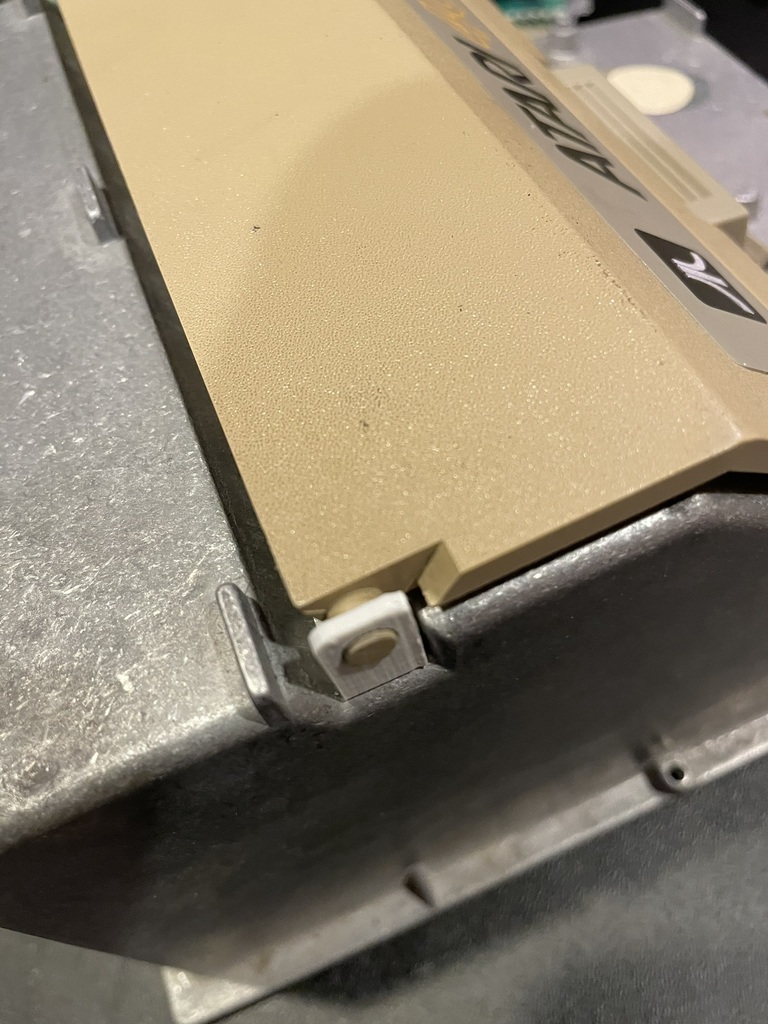
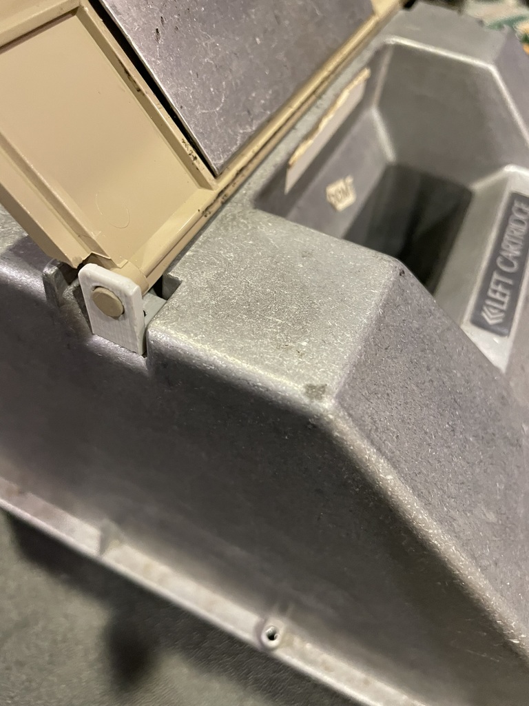
To replace the missing hinge bracket, I drew one up on Fusion 360 and printed it out. It fits quite nicely. The design is on Thingiverse

Replacement hinge bracket from the Atari 400 cart door.


Tuesday, September 21, 2021

FujiNet or Where's Jeff?

Over a year ago I fell in league with some Atari people developing a new peripheral device for the 8-bit line. The FujiNet is a nearly all-in-one SIO device for the Atari 400/800/XL/XE line of personal computers. It is capable of emulating disk drives, cassette drive, printers, and modem while providing a new network (N:) device. It is based on the ESP32 wifi-enabled MCU. Thom is our ring leader and Mozzwald our hardware designer. I'm grateful for being included and for my teammates. This project is a perfect COVID survival activity. 

FujiNet is why I stopped blogging projects - all my project energy was directed to FN development. What a huge technical distraction! I've been mainly a supporting developer (e.g., doing initial integration of code into the Platform.IO environment). I made most of the printer emulators, many with original fonts based on real Atari printer output found in manuals or obtained from the community. I collected and/or wrote printer test programs for verifying the emulator behavior. My most recent contribution was the cassette drive emulator; I'm still debugging writing cassette data to a CAS image. 


My collection of FujiNet hardware spanning the first ESP8266 unit to the pre-release version 1.6.


Saturday, February 29, 2020

Atari POKEY Actuation with Arduino

I've had floating in the back of my mind wanting to make a modern controller adapter for the Atari 5200. The 5200 controller is an analog joystick, two buttons, and a keypad. There are some modern controller projects that are really cool. As far as I can tell, they use digitally-controlled resistors to actuate the potentiometer inputs on the POKEY chip. Makes sense because that's what they were designed for - reading resistors.

The POKEY, along with a few external components, basically measures the time constant of an RC circuit. The system has an 1800-ohm resistor and 0.047 uF capacitor internal and the controller or paddle has a 0.5-1 M-ohm potentiometer. This makes for time constants ranging from <100 us to >10 ms. The operation is described in section 4 of the POKEY datasheet. The RC circuit can be seen in this excerpt of the 5200 schematic. The components on P0 (pin 14) are labeled.

The inputs P0-P7 are fed to Schmidt trigger inverters, which will go from high-to-low when the capacitor voltage reaches about 2 volts. The time that takes is determined by the resistance of the potentiometer. In otherwords, the time it takes to charge up the capacitor is measured by the POKEY.

Another way to charge the capacitor is to send in pulses of current (charge) over some time. I wondered if I could use the pulse width modulation (PWM) feature on modern microcontrollers, like the Atmega 328p used in the Arduino, to control how fast the capacitor charges. I had limited success. It turns out the PWM resolution required is much too fine. I would have to resort to additional timers and interrupts to fiddle with the PWM duty cycle and frequency.

Timers. Time. Hmmm. Charge up the capacitor at the right time!

Inside the POKEY is also a "dump transistor" that discharges the capacitor to reset the circuit for the next frame and reading. This is done by hitting the POTGO line. It can be seen in this schematic, again from the datasheet:
It's easy to charge up the capacitor - just apply some voltage for a few 10's of microseconds. But how to know when to do it? The dump transistors will pull the input pin to ground. If I monitor the paddle inputs and watch for it to go low, I know when the capacitors are reset and can start counting. Then I can send the input high at just the right time to trigger the POKEY.

This is super simple. And I made it work in a straightforward proof-of-concept. Here's the circuit:

The diode stops output PIN 3 from pulling down input on PIN 2. I want the dump transistor inside the POKEY to do the pulling. The proof-of-concept code is just some level checking and delays. This code can be used to reliably create readings from 1 to 227. Code 228 is made by just doing nothing, although to transition between 227 and 228 could be jittery because of the code trying to sync back up with the POTGO signal. A software PLL might be a way forward.

#include <Arduino.h>

void setup()
{
  pinMode(3, OUTPUT);
  pinMode(2, INPUT);

  // try to charge up the POT capacitor until it takes
  while (digitalRead(2) == LOW)
  {
    digitalWrite(3, HIGH);
    delayMicroseconds(64);
    digitalWrite(3, LOW);
  }

  // wait until dump transistor is activated
  while (digitalRead(2) == HIGH)
  {
  }
}

void loop()
{
  //trial and error on logic analyzer to get PADDLE(0)=1 despite a second late pulse
  delayMicroseconds(2190); // count up until dump transisstor is released
  delayMicroseconds(6350*2); // delay 100 line groups
  delayMicroseconds(636*2+63*5); // delay 10 & 1 line groups

  // charge up POT capacitor
  digitalWrite(3, HIGH);
  delayMicroseconds(63);
  digitalWrite(3, LOW);

   // wait until dump transistor clears cap with some debounce
  while (digitalRead(2) == HIGH)
  {
  }
  while (digitalRead(2) == HIGH)
  {
  }
}


Monday, November 25, 2019

Combo SIO2Arduino and RVERTER WiFi Modem for Atari 8-bits

I decided to glom Whizzosoft's SIO2Arduino and Paul Rickards' wifi modem together into a single ESP8266. It boots a single ATR file stored in SPIFFS. I demoed SIO2Arduino in a previous post.

Here's a video of it in action.


The code is on my GitHub.

Since doing this, I've joined the FujiNet development team to make something cooler.

Sunday, November 17, 2019

Atari on Papilio DUO

A few years ago I bought myself a Papilio DUO FPGA board. I was attracted to its Adruino Mega form factor and inclusion of an AVR Atmega32U4 chip. The IDE was based on the Arduino IDE. How cool - learn FPGAs inside what looked like the Arduino ecosystem. It also came with different shields - I bought the compute shield because it had joystick ports. Joystick ports. Did I say joystick ports? 

I ran through some demos and then set it aside. A year ago I started using is a logic analyzer for my Atari cartridge interface project. Recently, I decided to finally load up the Atari800 core I'd read about. I didn't do much research when I bought the board in 2015. Had I understood more, I probably would have bought a MIST, although the Papilio was about half the price I imagine. But I digress.


Thankfully, 64KiB.com (aka foft) ported the Atari FPGA implementation to the Papilio DUO. It loaded just fine, but it acted like the down arrow on the keyboard was stuck. Fortunately, the Papilio and 64KiB creators had already solved this problem.The AVR needed to be programmed for high-impedance inputs on all GPIOs. Whew. 

[NOTE: the website for the FPGA cores has moved to http://www.64kib.com/]

Another problem I ran into is keyboard mapping. I have a US-layout PS2 keyboard, which has a different layout of where the Atari arrow keys go compared to a UK-layout. I could only make the Atari cursor go in 3 directions. So RTFM and I learned about the UK-layout problem and started randomly trying CTRL-key combos. "CTRL-\" worked for me.

I played my GRAVITEN game, which was the second I wrote for the BASIC game competition. Fun.

Friday, June 14, 2019

Good Timing

In my last retrochallenge post I reported difficulty latching the address bus. Using the logic analyzer, I saw the latch signal was coming a but too late relative to the hold time of the address bus. I needed a way to edge trigger a shorter pulse. I found this handy circuit which creates a positive edge triggered pulse.

The pulse width is set by the RC time constant. I selected the resistor value to limit the current being sourced and sunk by the NAND gate (configured as an inverter). A value of 390 ohms limits the current to 13 mA peak, which is a 50% derating on the 25 mA absolute max allowed value for a LS74HCT00 device. The current spikes are short as they charge/discharge a small capacitor of a couple hundred pF to set the pulse width to 140 ns. I picked the cap somewhat by trial and error. The resulting timing looks like this:

The LE_D signal triggers the pulse generator, which outputs LE_A. The LE_A signal successfully latches the address before it changes right after the falling edge of phi2. 

Fortunately, I was able to use spare NAND and AND gates and only had to add the two passives. Almost free! Being able to latch the address allows the Atari handler and MCU software to be written to use a command/data protocol. The address specifies the command and the data shows up on the bus. I wonder what is possible with such an interface.

Friday, April 5, 2019

Retrochallenge 0319 - Last Post

I had to take a week off of the Retrochallenge to take care of life. I finished the month by making a completed circuit on a breadboard with mostly neat wires. I ran into trouble reading the address bus. The timing is too tight, so I need to change the latch signal for the address buffer.

The Retrochallenge is a good excuse to make some progress and to share the useless tinkering of the hobby. Here's what I have to show for it:

Thanks for following along!

Friday, March 22, 2019

The Flip Flop

I'm flip flopping like a politician on the data read algorithm in the Atmega328P MCU interface to the cartridge port. As described in previous posts, I was using an edge-triggered interrupt to alert the MCU that new data was ready. I chose the interrupt method because the original design was implemented on a single ESP32 that handled both the cartridge and wifi interfaces. The handling of the two interfaces was inherently asynchronous because they were both reacting to their external counterparts. The cartridge side didn't know when the Atari would push data and likewise with wifi and remote server. This didn't work very well given my rudimentary MCU programming skills. Splitting the system into two MCU's fixed the problem. It also allows a flip-flop to be made.

Researching this project, I ran across a website from Poland (that I can't find now) on interfacing to the 6502 bus. They used an SR flip-flop to latch the write enable signal before sending it to an MCU. The MCU could then poll the signal for a state change. While the interrupt method allows for simpler decoding logic, the polling makes for simpler software. And it's faster. The interrupt takes about 3 microseconds (several 6502 clock cycles). The polling can respond in half a microsecond or about a single 6502 cycle. This will add up to many saved clock cycles on the Atari side in the end.

Here's the concept.

The LE line goes low when the 6502 performs a STA $D5xx (described in this RC2019/03 post). The LE signal SETS the SR flip flop and its output Q tells the MCU it's time to read the data and address. The read operation is described here. Note, now the time between the LE going high and the /OEDATA going low is < 1 microsecond. It used to be 3 microseconds. Then the MCU sends a RESET to the SR flip flop and goes on to its next operation ...

... which is what I'm going to do, too.

Tuesday, March 12, 2019

NOP

The architecture of my Atari cartridge port interface adapter to an ESP8266 is to use an Arduino Nano (ATmega328P MCU) as an intermediary. Another way is to use an FPGA, but that's more costly and I don't have enough experience to try that yet. Using an MCU on the cartridge port, which is really just the 6502 bus, calls for the use of 3-state latches to capture and to hold data in place while the two microprocessors go about their business. While there is a flashcart out there that uses a 32-bit STMicro MCU to respond with 6502-bus timing, I'm not confident I can do that with a 16-MHz 8-bit MCU.

I've run into several challenges. First, what DIO pins should I use? I ended up splitting the 8-bit bus into two 4-bit nybbles spread between ATmega328P Ports D and B. The Arduino doesn't have an entire 8-bit port free. Reading the port requires some fun bitmath. Second, the output enable is sent out over a pin on Port C right before the 8-bit data is read. The 16-MHz is so fast, I had to throw in a NOP instruction to properly read the data. The enable time of the SN74HCT573 (/OE->Q) is at least 40 ns. Assuming the ATmega changes its output pin state at the end of it's clock cycle and begins its read at the start of the next, there's not enough time for the latch to output its data. A single NOP on the ATmega is 62.5 ns, more than the enable time on the latch. Or, maybe the ATmega328P digital input has some setup time that's otherwise violated. Either way, some brief testing indicates no missing bits.

The third challenge is related to the second - the disable time on the latch is also at least 40 ns. I want to read the address latch and the data latch sequentially. To avoid bus contention, the second latch cannot be enabled until after the first latch is fully disabled. This problem was solved by moving some instructions around inside the interrupt routine to put some delay between the two read operations.

Here's a logic analyzer plot showing the timing:
The disable time (OED rising edge to Q0 rising edge) is much longer than expected. But the Arduino C++ interrupt code arrangement makes the timing work out:

The interrupt routines reads two bytes and increments a counter, all in less than 5 microseconds. I put the counter increment in between the two reads to give the first latch time to disable before the second latch is enabled, which avoids bus contention. Cool.

Sunday, March 10, 2019

Schematic

Worked on a schematic this weekend ahead of adding more components to the circuit. I decided to include a buffer to grab the 8-bit address when the Atari executes a STA $D5xx instruction. I figure I can use the 8-bits to add some features or make the protocol simpler.
Excerpt of the schematic showing the Atari 8-bit cartridge edge connector, address and data buses, and decoder logic.

I use the free "maker" version of Autodesk Eagle. Here are the Eagle libraries used in the design:

  • Atari 800 parts, including a cartridge board, is at AtariAge
  • Arduino Nano pinout/footprint on Github
  • NodeMCU (esp8266 board) pinout/footprint on Github.
  • 74xx-eu built-in libary. This library had the HCT logic family where the US version did not. I'm not sure that really matters, but just in case....
I am grateful to the generosity of the individuals and organizations who make the tools and information freely available for hobbyist and maker use. That makes fun hardware projects like this possible. 

Wednesday, March 6, 2019

Unintended Interrupt

Most of the time spent on a hardware project is solving problems. I ran into an interesting one on my Arduino Nano: sending a digital out high on one pin was causing the hardware interrupt on another pin to trigger. What? Turns out my test setup was causing the problem. A bad case of the observer effect.

The Nano is biased at 5 V, which makes it easy to interface to the Atari. However, my FPGA-based logic analyzer is only 3.3 V compliant, so I need a level translator in between. I'm using a small 4-bit translator based on a single-FET design. These are often used with I2C interfaces. 

I was stumped by the false interrupts and couldn't find anything like it online. It drove me to read the Atmega 328 data sheet. At least I have a better understanding of the microcontroller and its interrupts. I finally went back to something I knew worked: turn the on-board LED on and off using an external interrupt. I then started changing the output pin #, which worked until it landed on the one I was monitoring with the logic analyzer. Ack! Grasping at straws, I tried adding pull up and pull down resistors to no avail. Then I realized the false interrupts only occurred when the output changed from low to high.

Maybe translator was sinking or sourcing too much current on the Nano's push-pull output drive? The typical diagram I see with these translators show effectively open drain outputs, so maybe I'm not using it in its intended application. It also turns out these things pull current when the signal is low. I think that suddenly applying a high causes the translator to load down the output with too much current, causing a malfunction on the IO bus.

I fixed it by putting a 330-ohm resistor in series between the output and the translator.

Whew.


Saturday, March 2, 2019

Decoder

Although this is a rebuild of my early breadboard using a new microcontroller, I want to go step-by-step to make sure each part works. The first circuit is a decoder to read the bus signals and generate a latch enable (LE) and an output enable (OE') for the interface buffers I will use between the Atari and the Arduino. Here's the logic diagram:
The cartridge port has a convenient Cartridge Control (CCTL') line that was intended to be used for bank switching. CCTL' goes low with an address of $D5xx. I want to be able to latch the data bus into a buffer with 6502 executes a STA $D500. This video has a nice explanation of 6502 bus timing and this page has a write enable circuit at the bottom, both of which gave me enough background to end up with this design.

I built this up using TI HCT logic, which you can still get in DIP packages. It uses one NAND (SN74HCT00) and one AND (SN74HCT08) chip.
I connect to the cartridge port using a breakout board and monitor the signals with a FPGA board running logic analyzer firmware. To cause LE to go high, the 6502 needs to execute STA $D500. I just used a POKE command in BASIC to do this easily:
The captured signals looked like this:
Note how the clock signal PHI2 gates the LE when the CCTL and R/W are both high. The resulting signal will be used to latch the data bus into a buffer and to interrupt the Arduino.

Thanks for reading.

Friday, March 1, 2019

Retro Challenge 2019/03

The advent of Arduino was great for hobby activities and getting back into tinkering with programming. An Atari computer fan(atic?) Thomas C. decided to resurrect the Atari's ability to connect to the PLATO system as a terminal and started up a vintage computing community dedicated PLATO system. You can get on the original PLATO system here. I found all this intriguing because I had been seeking to play the PLATO tank warfare game that is listed in Ernst Cline's Armada (Chronology). Who knew? Recently, Thomas C. asked if someone could interface a wifi modem to Atari's cartridge port. Why not take a crack at it?

I learned to program my Atari 400 then 800XL in BASIC during middle school. About that time, I became interested in how the machine worked and read about the ANTIC chip. I made my own character set, although I cannot remember how I learned to do that. I tried doing some player missile graphics (sprites), but never grasped it enough to use it. So I didn't understand enough to put it into practice.

I was also reading about robotics and wanted to control things. At this time, I told my father I wanted to learn how to "program hardware." He figured out what I meant was I wanted to design digital circuits. He was a mainframe system analyst and didn't know enough electronics to teach me (or maybe I had other more important interests) so it wasn't until college that I learned to design electronics. I also learned assembly programming on a Motorola 68HC11 microcontroller. Although I ended up going into microwave systems, I still dabble in embedded systems whenever I can.

For better or worse, I'm entering into the Retro Challenge 2019/03. Looking back at emails, I started this sometime in September 2018. In January 2019, I finally had a working prototype that seems to work without anomalies (no dropped characters, missed packets, etc.). I took a break in February to enter the BASIC 10 Liners. I don't know why I made the decision to not post earlier as I was developing, other than life gets in the way.

So, here's my rat's nest (starting point):


Thursday, February 21, 2019

reactorX - My 2019 BASIC 10 Liner

I've always been attracted to the strange arcade games. At the arcade in 1984, you might have found me wasting my quarters on Zaxxon. I didn't have to wait in line because no one else wanted to play it. But those isometric graphics lured me in. Gottlieb made some off beat games: Q-Bert, Mad Planets and Reactor. The sound on those machines is impressive and was authored by David Thiel.

I decided to create this year's 10 liner based on Reactor. I call it Reactor-X. It has three moving sprites plus the player's ship. Use your ship to bump the particles into the outer wall before the reactor core swells and goes into meltdown. Grab it over on my GitHub.
reactorX - 2019 BASIC 10 Liner Contest
The fast moving particles with complete multi-body collisions seen in this play-through were made possible using a new integer BASIC for the Atari called FastBasic. (I used Version 4.0.)

Instructions:
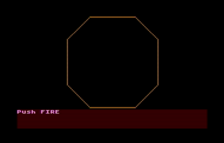
1. The opening screen shows the outer wall. Press the FIRE button to start.
2. You control the white +-shaped ship with your joystick. The three rogue atomic particles start on the other side of the core.
3. The particles do a random-walk while seeking out your ship. The bounce off of each other when they collide.
4. Gain points by hitting the particles with your ship.
5. The reactor core grows over time pushing your ship and the particles towards the deadly wall.
6. Use your ship to bump the particles towards the outer wall.
7. Be careful because the particles can bump you towards the wall, too! You have 5 lives.
8. Bump the particle into the wall to destroy it.
9. Two win, bump all three particles into the wall before the core swells too big!
Here's the compressed 10-line code:

Let's dig into the code:
data D() WORD = -1,1,2,2,1,-1,-2,-2,-1,1,2 Array to store info to draw an octagon. The drawing routine is at the bottom of the listing.
data x() WORD = 0,10,0,-10,0
data y() WORD = -20,20,20,20,0
Arrays to store X and Y positions of sprites with initial positions. Fifth index is the origin so I can reuse physics code.
dim alive(4), colsnX(4), colsnY(4) Arrays that store alive/dead state of PM's and changes in position due to collisions.
numkilled = 0
numlives = 5
score=0
rate = 15
counter = rate-1
Initialize some counters.
graphics 7
poke 752,1
Use 4 color 160x80 mode
Turn off cursor in text window
PM=$A000 mset $a000,1024,0
poke 54279,PM/256
poke 53277,3
poke 559,46
Clear out some RAM
 Tell ANTIC where PM RAM is' Enable PM display
Enable PM DMA with 2-line res
dpoke 704,$440F
dpoke 706,$4444
dpoke 709,$404F
Set colors for players 0 and 1,
players 2 and 3, and
the text window
x0=80
y0=40
color 1
radius = 19
exec octagon
Store the coordinates for the center of the screen.
Pick color 1, default is orange
Set the radius to draw the large octagon. Call the routine at the end of the listing.
?"Push FIRE" WHILE STRIG(0):WEND CLS Wait for player to start the game.
WHILE numkilled < 3 AND numlives> 0 This begins the main game loop
  alive(0) = 0 Reset the player is still alive flag.
  inc counter
  setcolor 1,counter,15
  if counter MOD rate = 0
    color 2
    radius = counter/rate
    exec octagon
  endif
Take care of the background graphics. Increment a counter to rotate the colors using the SETCOLOR command. Draw a larger octagon to enlarge the core every RATE game loop cycles. The EXEC OCTAGON jumps to the drawing routine at the end of the listing.
  poke 53248,x0+44+X(0)
  move adr(" -stuff-")+1, PM+$200 + y0 + 9 + Y(0), 17
Move player location. Poke the X coordinate and MOVE memory for the Y coordinate. The sprite is defined by the string, which starts at one byte higher than the address in FastBasic.
  for i=1 to 3
    move adr(" ball " ) + 1, PM + $200 + i*128 + y0 + 9 + Y(i), 14
    poke 53248+i,(x0+43+X(i))*(alive(i)=0)
  next i
Loop to move each  particle location. If particle is dead, keep it off the screen.
  poke 53278,1
  PAUSE 1
Clear collision register and paint the screen once to record collisions.
  for i=0 to 3 Loop through all the PM's
    colsnX(i) = 0
    colsnY(i) = 0
Initialize the collision accumulators...
    PiPF = peek(53252+i) Check the player-player collision register.
    if PiPF&1 = 1
      alive(i) = 1
Someone hit the wall! Set the alive/dead flag.
      if i = 0
        X(i) = 0
        Y(i) = -2*radius
        dec numlives
        mset PM+$200,128,0
        exit
It was the player's ship. Reset it's position and take away a life. Exit the collision detection loop.
      else
        X(i) = -43-x0
        inc numkilled
      endif
It was a particle. Kill it and remove it from the screen.
    elif PiPF&2 = 2
      freq = 80
      j=4
      exec bounce
    endif
Something hit the core. Make it bounce and get ready to play a tone.
    PiPj = peek(53260+i) Now check for player collisions. The 'i' value is subject player and 'j' value is player that was hit.
    if PiPj > 0 Act if there was a collision.
      if PiPj&1 = 1
        freq = 40
        j = 0
        score=score+5
The ship made a hit. Get some points and get ready to play a high-pitched tone.
      elif PiPj&2 = 2
        j = 1
      elif PiPj&4 = 4
        j = 2
      elif PiPj&8 = 8
        j = 3
      endif
Check for collisions with the particles.
      exec bounce Compute bounce position change.
    endif
  next i
Close the loop.
  if freq>0
    sound 0,freq,10,15
  else
    sound
  endif
  freq = 0
Play a tone or stop the tone, if needed.
  for i=1 to 3
    X(i)=X(i) - SGN((X(i)-X(0))/10) + colsnX(i) + RAND(3)-1 -(X(i)/33)
    Y(i)=Y(i) - SGN((Y(i)-Y(0))/10) + colsnY(i) + RAND(3)-1 -(Y(i)/33)
  next i
Update particle locations: attract to player, add in the bounce, do a little random walk, and stay away from the walls.
  P.657,2
  ? score, numlives;
Update the scoreboard. The POKE command positions the cursor before printing to the screen.
  S=STICK(0)
  LR=(S&4=4)-(S&8=8)
  UD=(S&1=1)-(S&2=2)
  Y(0) = Y(0) + colsnY(0) + UD+UD
  X(0) = X(0) + colsnX(0) + LR+LR
Get joystick input and move the player. Also add in the player bounce move.
WEND End of game loop.
SOUND Game over. Stop the sound.
if numkilled=3 and alive(0)=0 
  ?;"You Win!";
else
  ?;"/MELTDOWN\";
endif
Figure out the result.
do
loop
Wait forever.
proc bounce
  colsnX(i) = colsnX(i) + 2*SGN(X(i)-X(j))
  colsnY(i) = colsnY(i) + 2*SGN(Y(i)-Y(j))
endproc
Procedure to add in bounce motion. The motion is towards the ith particle and away from the jth particle. When j=4, the motion is away from the origin.
proc octagon
  plot x0-radius, y0 + 2*radius
  for p = 1 to 8
    drawto x0 + D(p)*radius, y0 + D(p+2)*radius
  next p
endproc
Procedure to draw an octagon. Loop through the vertices and draw lines. Scale the size by 'radius.'

Sunday, March 4, 2018

DEFENDER - 2018 BASIC 10-Liners Game Contest Entry

My first (and maybe only) entry to the 2018 10-Liner BASIC Game competition is an Atari Turbo-BASIC XL implementation of the 1981 arcade game DEFENDER.
It is entered into the EXTREM-256 line-length category. Defender is a side-scroller, which is why I chose to try it. I had been trying to figure out how to do fast horizontal scrolling with BASIC and eventually landed on the technique used here. Find it over on GitHub or download the auto-loading ATR file.

The Atari ANTIC video processor is driven by a micro program called a Display List (DL). The DL has one entry per line of graphics and defines a number of things including the graphics mode and an optional starting address for the data. As described in De Re Atari, one uses an expanded screen memory and merely specifies the starting address for each line of graphics to be displayed. In an assembly language program, the starting addresses can be updated during a vertical blank. The trouble with BASIC is that computing and poking addresses inside FOR-NEXT loop is not nearly fast enough to be satisfactory. I realized instead, I could build a precomputed look up table (LUT) and store it in RAM. Then using Turbo-BASIC's MOVE command, I could rapidly update the display list with the appropriate data to get fast side scrolling.

Once I had the side scrolling, everything else slowly fell into place. I created a random mountain generator. I wanted a radar display. Then I had to compromise on the AI's because the computational load was getting a little high for the game loop. I developed the AI's in graphics mode 0 with only 40 columns of playfield. This was enough to see the overall behavior and get a satisfactory result. Here's a screenshot of the final prototype. See the "(" kidnapping the "$"?
At this point, my program was 12 lines long. I settled on static bad guys except for special abductors who descend to kidnap your citizens. If you successfully terminate an abductor in the act, the citizen gracefully floats to earth. Be careful not to takeout a citizen accidentally - friendly fire is gruesome but challenging.

The Code

Here's the obfuscated 10-liner produced by DSMC's tbxl-parser.
The most straightforward code to analyze is here. It doesn't use any compression techniques and the AI code is separated out for each character type. This code parses into too many lines. The first task I did was to copy the compression techniques developed by Victor Parada for Space Ranger. This got be down another line. Then I tackled the AI logic, which had lots of duplicated commands to update the playfield and radar display. I matched up the AI's with the most common logic and screen update code and combined them together. This got me down to 10 lines plus the ?"game over" statement. I then found two POKES which I combined into a single DPOKE. That did it. 

Here's the final source file with expanded comments:
'-----------------------------------------------------------
'
'                       DEFENDER
'
'For Atari 800XL 8-Bit BASIC 10-Liner
'One-player game with joystick
'
'Jeff Piepmeier
'January 31, 2018
'
'--Parsed with TurboBASIC XL Parser Tool 
$options +optimize
'-- Tested on Altirra
'-- bitmap graphics developed with Mad Studio
'-- POKE/MOVE compression technique copied/adapted 
'from Victor Parada's Space Ranger
'-----------------------------------------------------------

First is a very long string of ATASCII for storing addresses and data. The first 6 characters are a very short display list described below. Then there are 8 pokes and some player-missile data followed by some POKEY sound settings.

'a whole bunch of data for POKES and MOVES
A=ADR("\46\62\BF\41\50\A0\6F\A0\00\07\D4\B0\C0\02\08\1D\D0\03\6F\02\31\2F\02\3E\F4\02\B8\62\BF\E2\04\08\D0\01\03\03\03\04\C4\02\0E\36\D6\88\03\AC\A0\41\50\A0\04\56\A0\00\4E\50\A1\08\20\B8\30\38\30\20\70\20\20\70\08\28\B8\7C\D6\D6\7C\38\7C\54\92\14\2A\B3\90\90\90\90\90\90\90\90\90\90\90\90\90\90\90\90\90\90\90\90\06\04\B2\20\70\F8\7E\FF\70\06\0E\B2\04\0E\1F\7E\FF\0E\04\00\D2\C0\AF\C1\AF\00")

'make a string of spaces to use a couple different places
DIM A$(4)
A$="    "

I use graphics mode 15 because it's well suited to the radar display and it zeros out a whole bunch of RAM. There's enough RAM to contain the radar, playfield, PM graphics and custom character set. Here's the memory map I made to keep track of everything:
C000-------------
Text Screen
BF60-------------
BC00-------------
Character Set
B800-------------
Player 3
B700-------------
Player 2
B600-------------
Player 1
B500-------------
Player 0
B400-------------
Missiles
B300-------------
B140-------------
Character GFX
A4C0-------------
Bitmap GFX
A150-------------
A0AB-------------
Display List
A050-------------
9FD0-------------
Look Up Table
7F00-------------

'base the memory map on graphics mode 15
GR.15

I move the text window to the first line of the screen and use graphics mode 2. The LUT takes so long to build, I decide to speed it up some by temporarily using a wait for vertical scan command right after the first line of text. This probably speeds things up 30-40%. I wanted to have a countdown displayed so the user would know the program was working.

'START: build new display list
'SHORTEN DISPLAY LIST SO STEAL FEWER CPU CYCLES one line of graphics 1 mapped to text window; wait for vertical scan
'MOVE ADR("\46\62\BF\41\50\A0"),$A053,6
MOVE A,$A053,6
A=A+6

The side-scrolling feature needs a look-up table (LUT) whose entries can be quickly copied into the display list to create the scroll. This nest loop computes the LUT and stores in RAM below the video.

'write coarse-scrolling LUT to RAM below video
FIELDWIDTH = 160
LUT=$7F00
ADDR=LUT
LINEONE=42176 : REM start of character graphics in video ram
FOR COLS=0 TO 139
    ? 139-COLS;A$;
    FOR ROWS=0 TO 19
        POKE ADDR,86 : REM GR.1 CHARACTER MODE; DP. TAKES 1 LESS CHAR THAN POKE
        DPOKE ADDR+1,LINEONE+COLS+ROWS*FIELDWIDTH
        ADDR=ADDR+3
    NEXT ROWS
    POKE 657,2
NEXT COLS

There are several POKE commands needed to set up the PM graphics - the addresses and data are stored in the giant string in the first line.

REM COMPRESSED CODE GOES HERE
FOR I = 1 TO 8
    POKE DPEEK(A),PEEK(A+2)
    A=A+3
NEXT I

The ROM character set is copied into RAM so it can be modified. The modifications are done by copying custom characters stored above into RAM and by remapping some of the characters to different locations. The remapping is done below.

'copy the ROM character set for modification
MOVE $E000,$B800,512

Copy data out of the string above in to RAM. This code is "borrowed" from http://www.vitoco.cl/atari/10liner/RANGER/. The first byte in the record is the number of bytes to be copied. The second two are the target 16-bit address. The remainder are the data. The process is repeated until a 0 is encountered. The very last move turns on two sound channels to create a beating low-E sound similar to the start of the arcade Defender.

REM # BYTES, TARGET ADDRESS (LO/HI), DATA
B=PEEK(A)
WHILE B
  MOVE A+3,DPEEK(A+1),B
  A=A+B+3
  B=PEEK(A)
WEND

I adapted this technique to be able to copy memory from one location to another. I move the ATASCII line art characters to a different location in the character set and I copy the bad guy character to multiple locations in the map. I need multiple copies because I use the character code to store the AI identities in the screen memory itself. This avoids needed to keep track of too many things with arrays.

'copy some memory around, including remapping some characters
A=ADR("\30\E2\08\B8\10\68\E2\18\B8\08\28\B8\30\B8\18\00\B8\48\B8\08\03\B2\10\B9\08\62\BF\63\BF\02")
FOR I=1 TO 6
    MOVE DPEEK(A),DPEEK(A+2),PEEK(A+4)
    A=A+5
NEXT I
REM END COMPRESSED CODE

I wanted to have the mountains in the play field and though having the randomly generated might be more compact that storing a predetermined set. This loop randomly picks up/straight/down directions on each iteration and draws the mountains on the playfield and radar. The ATASCII line art characters were remapped so the screen codes are 1, 2 and 3. This makes poking them into RAM straightforward. Also, they needed to be moved into the lower 64 characters to be accessible in graphics mode 2. Finally, note here and everywhere else below there are both POKE and PLOT commands to put things on the playfield and radar display. This dual display code in part forces me into the EXTREM-256 category.

'draw the mountains
QUARTER = 39 : REM 79-FIELDWIDTH/4, used in the radar display
COLOR 2
Y=1
FOR I=0 TO (FIELDWIDTH-1)
    'choose random slope
    R=RAND(3)+1
    'check for top or bottom boundaries
    R=R+(Y=0)*(R=1)-(Y=5)*(R=2)
    'increase height if needed
    Y=Y-(R=1)
    'insert character into last 5 rows of map
    POKE $A4C0+(Y+14)*FIELDWIDTH+I,R+64 
    PLOT QUARTER+I/2,15+Y
    'decrease height if needed
    Y=Y+(R=2)
NEXT I

This little bit draws the outline for the radar display. The radar display was an important feature to have for me. Besides just being darn cool, it allows the player to see if his citizens are being kidnapped.

'draw the RADAR outline
COLOR 3
PLOT 0,21 : DRAWTO 159,21
DRAWTO 78-40,21 : DRAWTO 78-40,0
DRAWTO 80+40,0 : DRAWTO 80+40,21

To speed up AI processing, I store abductors and citizens in a 2-D array. The abductors are initially hidden and coded with a value of 9 in the screen memory. The players are placed on the screen above the mountains so they can drop down. I take advantage of the AI behavior so I don't have to remember where the mountains are.

'generate abductors and victims
NA = 9
DIM AI(NA,2)
FOR I=0 TO NA-1
    REPEAT 
        PX = RAND(FIELDWIDTH) : REM X LOCATION OF PEOPLE
        PPX = LINEONE+13*FIELDWIDTH+PX 
    UNTIL PEEK(PPX)=0
    AI(I,1) = PPX : REM PLAYFIELD ADDRESS
    POKE PPX,$04 : REM INSERT PEOPLE
    AI(I,2) = LINEONE+PX
    POKE LINEONE+PX,NA : REM INSERT LATENT ABDUCTOR, NA HAPPENS TO = 9 which is char code
NEXT I

I initially tried to have the other bad guys move around, but it just was too slow, took too much code space and didn't add much to the game play. So they are static and simply inserted into the screen. There's a small chance of 1:1440 that one will be placed right where the hero's ship starts. It's only happened to me once during testing. I didn't try to squeeze in logic to avoid that - I suppose a single POKE of a 0 into that location would do the job. Alas.

'generate some static bad guys
'always slim chance one lands on ship at start, but that's a feature
FOR I=1 TO 20
    REPEAT 
        X = 10+RAND(FIELDWIDTH-20)
    UNTIL PEEK(LINEONE+X)=0
    Y = 1+RAND(12)
    BB = LINEONE+X+Y*FIELDWIDTH
    POKE BB, $85 : REM PUT DOWN BADDIES
    PLOT QUARTER+((BB-LINEONE) MOD FIELDWIDTH)/2,Y+1
NEXT I

This bit initializes the game play: sets the starting location and direction of the ship; initialize the citizen and lives counters (the score starts at 0 already since you don't have to initialize variables in BASIC). The countdown timer is set to 5000.

'start the ship in the middle of the play field
XWLD = 70
'point the ship to the left
DX=-1
PY=$3E : REM POSITION THE Y-LOCATION SO SHIP LOCATIONS OVERLAP CHARACTER LOCATIONS
'SCORE=0
PEOPLE=NA
LIVES=3
POKE $D000,120
PM=$B440:REM PM*$100+$200 TO POINT TO FIRST PLAYER
T0=TIME+5E3

And turn off the sound before play starts. I had so much code below, I didn't even try to create sound effects.

'turn off the sound
SOUND

Whew, finally made it to the main game loop. Interestingly enough, I found all my games take about half the lines for the setup and the other half for the game loop. Defender is not so different - the game loop starts in the middle of 5th line. I have REM statements on many of the lines and will only add expanded comments where they add.

REPEAT
    TT=T0-TIME : rem countdown timer
    POKE 657,6 : rem position cursor for time display
    ?TT;A$; 
    POKE 657,13 : rem position cursor for VICTIMS and SCORE display
    ?PEOPLE;A$;SCORE;

    REM PROCESS FIRE BUTTON
    F0=F
    F=STRIG(0)
    FIRE=F0&(1-F) : REM DISABLE RAPID FIRE
    FY=PY*FIRE+FY*(1-FIRE) : REM REMEMBER Y-LOCATION OF LASER
    FOR I=1 TO 3
        POKE PM+I*$100+$08+FY,FIRE*$FF : REM ADD OR REMOVE LASER IN PLAYER : REM DP. TAKES 1 LESS CHAR THAN POKE : +$40 IS BAKED INTO PM
        POKE $D000+I,112+10*DX+18*DX*I :  REM POSITION LASER
        POKE 704+I,8+16*RAND(16) : REM SET A RANDOM COLOR
    NEXT I
    REM PROCESS HITS and COLLISIONS - combine together to avoid duplicate commands

This is the first bit of AI that I combined together to reduce the amount of code. I hope I can remember what is does!

First, check to see if either the firebutton was pressed of if there is a player-playfield collision.
    IF PEEK($D004)&4+FIRE
Once we're in, why we are in is stored in I
        I=FIRE
When the lasers are fired, we have to loop to clear out the bad guys.
        REPEAT 
The subject location is computed and stored in FPOS. Note the variable I is now being used as a counter.
            FPOS=TRUNC(LINEONE+RDRY*FIELDWIDTH+XWLD+10.5+I*DX)
Here the item in screen memory is grabbed. Only the lower 4 bits matter as the upper four indicate color.
            WHAT=PEEK(FPOS)&$0F
Check to make sure we don't shoot the mountains.
            IF WHAT>3
These next two lines were repeated a lot in the original code. Having to update both the playfield and the radar display takes space!
                'erase characters
                POKE FPOS,0
                C.0 : PLOT QUARTER + ((FPOS-LINEONE) MOD FIELDWIDTH)/2,RDRY+1
                'if hit a bad guy...
All the bad guys are characters > 4. I suppose a latent adbductor==9 could be destroyed, but I've tried and it's probably unlikely to occur.
                IF WHAT>4
                    SCORE=SCORE+100
                    IF I=0
                        'collided with a bad guy!
                        POKE $D000,0
                        LIVES=LIVES-1
                        POKE $BF62+LIVES,0 : REM DP. TAKES 1 LESS CHAR THAN POKE
                        VX=0
                        PAUSE 60
                        POKE $D000,120
                    ENDIF
                ELSE
                    'OOPS! hit a citizen!
                    PEOPLE=PEOPLE-1
If the citizen was being abducted, then turn the abductor $88 into a static bad guy $85.
                    IF PEEK(FPOS-FIELDWIDTH)=$88
                        POKE FPOS-FIELDWIDTH,$85
                    ENDIF
                ENDIF
            ENDIF
        I=I+1
If we entered the loop because of a collision, the I was 0 and is now 1. That will exit. If we entered because we fired, then I was 1 and is incremented until I=10.
        UNTIL (I=1) ! (I=10) : REM OR IMOD9=1
    ENDIF
    POKE $D01E,1 : REM HITCLR
    
    REM PROCESS STICK INPUT
    S=STICK(0)
    UD=(S&2=0)*(PY<145)-(S&1=0)*(PY>0)
    PY=PY+4*UD : REM LIMITS 46144 , 46288 B440-B4D0
    LR=(S&8=0)-(S&4=0) : REM CREATE +/1 VALUES FOR LEFT/RIGHT
I use an IIR discrete time filter to create acceleration/deceleration effects.
    VX = VX/2 + LR/2 : REM USE IIR FILTER FOR ACCELERATION/DRAG EFFECT
    DX = DX*(LR=0)+LR : REM DIRECTION INDICATOR
    XWLD = (XWLD + VX + 139) MOD 139 : REM UPDATE HORIZONTAL POSITION IN WORLD COORDINATES
Because the X coordinate is floating point, I can do both coarse and fine scrolling. The fraction and truncation commands are taken advantage of here:
    XF=FRAC(XWLD)*8 : REM FINE SCROLL VALUE
    XT=LUT+TRUNC(XWLD)*60 : REM COARSE SCROLL VALUE

The missile portion of the PM graphics are used to indicate the location on the radar. These few lines move the ship.
    REM MISSILE SPRITES FOR RADAR POSITION INDICTATOR
    POKE $B32A+RDRY,$90 : REM RADAR INDICATOR OLD POSITION
    RDRX = TRUNC(XWLD/2)+87 : REM CONVERT WORLD COORDINATE TO RADAR COORDINATE
    RDRY = TRUNC((PY+6)/8) : REM RADAR Y FOR SHIP -6 TO 146 -> 0 TO 19
    POKE $B32A+RDRY,$91 : REM PUT SHIP ON RADAR

Next we update the display list, but wait for a vertical blank to avoid flicker. I tried this on real hardware and it seems to work well.
    PAUSE 0 : REM WAIT FOR VERTICAL BLANK TO REDUCE FLICKER
    POKE $D404,12-XF : REM FINE SCROLL
    MOVE XT,$A070,60 : REM COPY IN DL FOR COARSE SCROLL
    DPOKE $D006,257*RDRX+11 : REM MOVE INDICATORS IN RADAR DISPLAY
    'POKE $D007,RDRX
    POKE $D004,RDRX+5 : REM MOVE THE SHIP IN THE RADAR DISPLAY
    MOVE $B205-5*DX,PM+PY,14 : REM PUT SHIP ON THE SCREEN (+$40 IS BAKED INTO PM)

This last set of conditionals processes the AI behaviors. Combining multiple cases into one logic flow was critical to fitting in the 10 lines. Here goes...    
    REM PROCESS AI
    REM PROCESS PEOPLE THEN ABDUCTORS
There are abductors and citizens. Using the FOR loop, I process the citizens first, then the abductors.
    FOR I=1 TO 2
The pointer to screen memory location is retrieved
    LL=AI(IDX,I)
If it is valid, then proceed. Otherwise, it must have been destroyed earlier.
        IF LL>0
            'something is there
Find out what the pointer is pointing to.
            PLL=PEEK(LL)
If it is a latent abductor $09, then flip a coin to see if it appears $87.
            IF PLL=9
                'if waiting abductor, maybe it now appears
                IF RND<.5
The screen code $87 is used to indicate a descending abductor.
                    POKE LL,$87
                ENDIF
            ELSE
If it wasn't an abductor, maybe it's something else
                IF PLL<>5
                    'if not a static bad guy ...
Look below the subject
                    LLP=LL+FIELDWIDTH
                    PLP = PEEK(LLP)
And above the subject
                    LLM = LL-FIELDWIDTH
Erase the subject so we can redraw it after moving it. Combining all the AI logic here avoids having to repeat these commands several times.
                    X = QUARTER + ((LL-LINEONE) MOD FIELDWIDTH)/2
                    Y = 1 + (LL-LINEONE) DIV FIELDWIDTH
                    COLOR 0 : PLOT X,Y
The screen code $88 indicates an ascending abductor that must have a kidnap victim.
                    IF PLL=$88
                        'if an ascending abductor it must also have a citizen
Erase the kidnap victim on the radar. 
                        PLOT X,Y+1 : REM IS COLOR 0
Find out if the abductor is still going up or maybe can escape at the top:
                        IF LLM>LINEONE
                            'still going up
Erase the citizen from the play field, move the ship up one line. 
                            POKE LLP,0
                            POKE LLM,PLL
Remember where the abductor is.
                            AI(IDX,2)=LLM
Replot the citizen below the ship.
                            POKE LL,4
Remember where the citizen is.
                            AI(IDX,1)=LL
Redraw them on the radar.
                            COLOR 1 : PLOT X,Y
                            COLOR 3 : PLOT X,Y-1
                        ELSE
If the abductor escapes, erase them, set their locations to invalid, and reduce the citizen count.
                            'escaped with a citizen!
                            POKE LLP,0
                            POKE LL,0
                            AI(IDX,1)=-1
                            AI(IDX,2)=-1
                            PEOPLE=PEOPLE-1
                        ENDIF
                    ENDIF
If the subject is a citizen or descending abductor, deal with them now
                    IF (PLL=4)!(PLL=$87)
                        IF PLP=4
If there a citizen below the abductor, then kidnap them!
                            'descending abductor
                            POKE LL,PLL+1
                        ELSE
                            'falling citizen who was rescued or descending abductor!
This logic was tricky and I only figured it out by working out the individual one separately at first. If there's space below the subject and either space above the subject or the subject is an abductor then...
                            IF (PLP=0)&( (PEEK(LLM)=0)!(PLL=$87) )
Erase the subject and move it down one line. That works for either one.
                                POKE LL,0
                                POKE LLP,PLL
Update the location of the subject.
                                AI(IDX,I)=LLP
                                Y=Y+1
                            ENDIF
Put the subject back on the radar. The subject is $87, then use color 3.
                            COLOR 1 + (PLL&2) : PLOT X,Y
                        ENDIF
                    ENDIF
                ENDIF
            ENDIF
        ENDIF : REM LL>0
    NEXT I
Move onto the next set of AI's
    IDX=(IDX+1) MOD NA
And keep on going until out of time or the hero is dead.
UNTIL (TT<0) ! (LIVES=0)
POKE 657,2
?"game over";
That's it!

Thanks for reading! I hope you get a chance to play and have fun.