Monday, November 25, 2019

Combo SIO2Arduino and RVERTER WiFi Modem for Atari 8-bits

I decided to glom Whizzosoft's SIO2Arduino and Paul Rickards' wifi modem together into a single ESP8266. It boots a single ATR file stored in SPIFFS. I demoed SIO2Arduino in a previous post.

Here's a video of it in action.


The code is on my GitHub.

Since doing this, I've joined the FujiNet development team to make something cooler.

Sunday, November 17, 2019

Atari on Papilio DUO

A few years ago I bought myself a Papilio DUO FPGA board. I was attracted to its Adruino Mega form factor and inclusion of an AVR Atmega32U4 chip. The IDE was based on the Arduino IDE. How cool - learn FPGAs inside what looked like the Arduino ecosystem. It also came with different shields - I bought the compute shield because it had joystick ports. Joystick ports. Did I say joystick ports? 

I ran through some demos and then set it aside. A year ago I started using is a logic analyzer for my Atari cartridge interface project. Recently, I decided to finally load up the Atari800 core I'd read about. I didn't do much research when I bought the board in 2015. Had I understood more, I probably would have bought a MIST, although the Papilio was about half the price I imagine. But I digress.


Thankfully, 64KiB.com (aka foft) ported the Atari FPGA implementation to the Papilio DUO. It loaded just fine, but it acted like the down arrow on the keyboard was stuck. Fortunately, the Papilio and 64KiB creators had already solved this problem.The AVR needed to be programmed for high-impedance inputs on all GPIOs. Whew. 

[NOTE: the website for the FPGA cores has moved to http://www.64kib.com/]

Another problem I ran into is keyboard mapping. I have a US-layout PS2 keyboard, which has a different layout of where the Atari arrow keys go compared to a UK-layout. I could only make the Atari cursor go in 3 directions. So RTFM and I learned about the UK-layout problem and started randomly trying CTRL-key combos. "CTRL-\" worked for me.

I played my GRAVITEN game, which was the second I wrote for the BASIC game competition. Fun.

Friday, June 14, 2019

Good Timing

In my last retrochallenge post I reported difficulty latching the address bus. Using the logic analyzer, I saw the latch signal was coming a but too late relative to the hold time of the address bus. I needed a way to edge trigger a shorter pulse. I found this handy circuit which creates a positive edge triggered pulse.

The pulse width is set by the RC time constant. I selected the resistor value to limit the current being sourced and sunk by the NAND gate (configured as an inverter). A value of 390 ohms limits the current to 13 mA peak, which is a 50% derating on the 25 mA absolute max allowed value for a LS74HCT00 device. The current spikes are short as they charge/discharge a small capacitor of a couple hundred pF to set the pulse width to 140 ns. I picked the cap somewhat by trial and error. The resulting timing looks like this:

The LE_D signal triggers the pulse generator, which outputs LE_A. The LE_A signal successfully latches the address before it changes right after the falling edge of phi2. 

Fortunately, I was able to use spare NAND and AND gates and only had to add the two passives. Almost free! Being able to latch the address allows the Atari handler and MCU software to be written to use a command/data protocol. The address specifies the command and the data shows up on the bus. I wonder what is possible with such an interface.

Friday, April 5, 2019

Retrochallenge 0319 - Last Post

I had to take a week off of the Retrochallenge to take care of life. I finished the month by making a completed circuit on a breadboard with mostly neat wires. I ran into trouble reading the address bus. The timing is too tight, so I need to change the latch signal for the address buffer.

The Retrochallenge is a good excuse to make some progress and to share the useless tinkering of the hobby. Here's what I have to show for it:

Thanks for following along!

Friday, March 22, 2019

The Flip Flop

I'm flip flopping like a politician on the data read algorithm in the Atmega328P MCU interface to the cartridge port. As described in previous posts, I was using an edge-triggered interrupt to alert the MCU that new data was ready. I chose the interrupt method because the original design was implemented on a single ESP32 that handled both the cartridge and wifi interfaces. The handling of the two interfaces was inherently asynchronous because they were both reacting to their external counterparts. The cartridge side didn't know when the Atari would push data and likewise with wifi and remote server. This didn't work very well given my rudimentary MCU programming skills. Splitting the system into two MCU's fixed the problem. It also allows a flip-flop to be made.

Researching this project, I ran across a website from Poland (that I can't find now) on interfacing to the 6502 bus. They used an SR flip-flop to latch the write enable signal before sending it to an MCU. The MCU could then poll the signal for a state change. While the interrupt method allows for simpler decoding logic, the polling makes for simpler software. And it's faster. The interrupt takes about 3 microseconds (several 6502 clock cycles). The polling can respond in half a microsecond or about a single 6502 cycle. This will add up to many saved clock cycles on the Atari side in the end.

Here's the concept.

The LE line goes low when the 6502 performs a STA $D5xx (described in this RC2019/03 post). The LE signal SETS the SR flip flop and its output Q tells the MCU it's time to read the data and address. The read operation is described here. Note, now the time between the LE going high and the /OEDATA going low is < 1 microsecond. It used to be 3 microseconds. Then the MCU sends a RESET to the SR flip flop and goes on to its next operation ...

... which is what I'm going to do, too.

Tuesday, March 12, 2019

NOP

The architecture of my Atari cartridge port interface adapter to an ESP8266 is to use an Arduino Nano (ATmega328P MCU) as an intermediary. Another way is to use an FPGA, but that's more costly and I don't have enough experience to try that yet. Using an MCU on the cartridge port, which is really just the 6502 bus, calls for the use of 3-state latches to capture and to hold data in place while the two microprocessors go about their business. While there is a flashcart out there that uses a 32-bit STMicro MCU to respond with 6502-bus timing, I'm not confident I can do that with a 16-MHz 8-bit MCU.

I've run into several challenges. First, what DIO pins should I use? I ended up splitting the 8-bit bus into two 4-bit nybbles spread between ATmega328P Ports D and B. The Arduino doesn't have an entire 8-bit port free. Reading the port requires some fun bitmath. Second, the output enable is sent out over a pin on Port C right before the 8-bit data is read. The 16-MHz is so fast, I had to throw in a NOP instruction to properly read the data. The enable time of the SN74HCT573 (/OE->Q) is at least 40 ns. Assuming the ATmega changes its output pin state at the end of it's clock cycle and begins its read at the start of the next, there's not enough time for the latch to output its data. A single NOP on the ATmega is 62.5 ns, more than the enable time on the latch. Or, maybe the ATmega328P digital input has some setup time that's otherwise violated. Either way, some brief testing indicates no missing bits.

The third challenge is related to the second - the disable time on the latch is also at least 40 ns. I want to read the address latch and the data latch sequentially. To avoid bus contention, the second latch cannot be enabled until after the first latch is fully disabled. This problem was solved by moving some instructions around inside the interrupt routine to put some delay between the two read operations.

Here's a logic analyzer plot showing the timing:
The disable time (OED rising edge to Q0 rising edge) is much longer than expected. But the Arduino C++ interrupt code arrangement makes the timing work out:

The interrupt routines reads two bytes and increments a counter, all in less than 5 microseconds. I put the counter increment in between the two reads to give the first latch time to disable before the second latch is enabled, which avoids bus contention. Cool.

Sunday, March 10, 2019

Schematic

Worked on a schematic this weekend ahead of adding more components to the circuit. I decided to include a buffer to grab the 8-bit address when the Atari executes a STA $D5xx instruction. I figure I can use the 8-bits to add some features or make the protocol simpler.
Excerpt of the schematic showing the Atari 8-bit cartridge edge connector, address and data buses, and decoder logic.

I use the free "maker" version of Autodesk Eagle. Here are the Eagle libraries used in the design:

  • Atari 800 parts, including a cartridge board, is at AtariAge
  • Arduino Nano pinout/footprint on Github
  • NodeMCU (esp8266 board) pinout/footprint on Github.
  • 74xx-eu built-in libary. This library had the HCT logic family where the US version did not. I'm not sure that really matters, but just in case....
I am grateful to the generosity of the individuals and organizations who make the tools and information freely available for hobbyist and maker use. That makes fun hardware projects like this possible. 

Wednesday, March 6, 2019

Unintended Interrupt

Most of the time spent on a hardware project is solving problems. I ran into an interesting one on my Arduino Nano: sending a digital out high on one pin was causing the hardware interrupt on another pin to trigger. What? Turns out my test setup was causing the problem. A bad case of the observer effect.

The Nano is biased at 5 V, which makes it easy to interface to the Atari. However, my FPGA-based logic analyzer is only 3.3 V compliant, so I need a level translator in between. I'm using a small 4-bit translator based on a single-FET design. These are often used with I2C interfaces. 

I was stumped by the false interrupts and couldn't find anything like it online. It drove me to read the Atmega 328 data sheet. At least I have a better understanding of the microcontroller and its interrupts. I finally went back to something I knew worked: turn the on-board LED on and off using an external interrupt. I then started changing the output pin #, which worked until it landed on the one I was monitoring with the logic analyzer. Ack! Grasping at straws, I tried adding pull up and pull down resistors to no avail. Then I realized the false interrupts only occurred when the output changed from low to high.

Maybe translator was sinking or sourcing too much current on the Nano's push-pull output drive? The typical diagram I see with these translators show effectively open drain outputs, so maybe I'm not using it in its intended application. It also turns out these things pull current when the signal is low. I think that suddenly applying a high causes the translator to load down the output with too much current, causing a malfunction on the IO bus.

I fixed it by putting a 330-ohm resistor in series between the output and the translator.

Whew.


Saturday, March 2, 2019

Decoder

Although this is a rebuild of my early breadboard using a new microcontroller, I want to go step-by-step to make sure each part works. The first circuit is a decoder to read the bus signals and generate a latch enable (LE) and an output enable (OE') for the interface buffers I will use between the Atari and the Arduino. Here's the logic diagram:
The cartridge port has a convenient Cartridge Control (CCTL') line that was intended to be used for bank switching. CCTL' goes low with an address of $D5xx. I want to be able to latch the data bus into a buffer with 6502 executes a STA $D500. This video has a nice explanation of 6502 bus timing and this page has a write enable circuit at the bottom, both of which gave me enough background to end up with this design.

I built this up using TI HCT logic, which you can still get in DIP packages. It uses one NAND (SN74HCT00) and one AND (SN74HCT08) chip.
I connect to the cartridge port using a breakout board and monitor the signals with a FPGA board running logic analyzer firmware. To cause LE to go high, the 6502 needs to execute STA $D500. I just used a POKE command in BASIC to do this easily:
The captured signals looked like this:
Note how the clock signal PHI2 gates the LE when the CCTL and R/W are both high. The resulting signal will be used to latch the data bus into a buffer and to interrupt the Arduino.

Thanks for reading.

Friday, March 1, 2019

Retro Challenge 2019/03

The advent of Arduino was great for hobby activities and getting back into tinkering with programming. An Atari computer fan(atic?) Thomas C. decided to resurrect the Atari's ability to connect to the PLATO system as a terminal and started up a vintage computing community dedicated PLATO system. You can get on the original PLATO system here. I found all this intriguing because I had been seeking to play the PLATO tank warfare game that is listed in Ernst Cline's Armada (Chronology). Who knew? Recently, Thomas C. asked if someone could interface a wifi modem to Atari's cartridge port. Why not take a crack at it?

I learned to program my Atari 400 then 800XL in BASIC during middle school. About that time, I became interested in how the machine worked and read about the ANTIC chip. I made my own character set, although I cannot remember how I learned to do that. I tried doing some player missile graphics (sprites), but never grasped it enough to use it. So I didn't understand enough to put it into practice.

I was also reading about robotics and wanted to control things. At this time, I told my father I wanted to learn how to "program hardware." He figured out what I meant was I wanted to design digital circuits. He was a mainframe system analyst and didn't know enough electronics to teach me (or maybe I had other more important interests) so it wasn't until college that I learned to design electronics. I also learned assembly programming on a Motorola 68HC11 microcontroller. Although I ended up going into microwave systems, I still dabble in embedded systems whenever I can.

For better or worse, I'm entering into the Retro Challenge 2019/03. Looking back at emails, I started this sometime in September 2018. In January 2019, I finally had a working prototype that seems to work without anomalies (no dropped characters, missed packets, etc.). I took a break in February to enter the BASIC 10 Liners. I don't know why I made the decision to not post earlier as I was developing, other than life gets in the way.

So, here's my rat's nest (starting point):


Thursday, February 21, 2019

reactorX - My 2019 BASIC 10 Liner

I've always been attracted to the strange arcade games. At the arcade in 1984, you might have found me wasting my quarters on Zaxxon. I didn't have to wait in line because no one else wanted to play it. But those isometric graphics lured me in. Gottlieb made some off beat games: Q-Bert, Mad Planets and Reactor. The sound on those machines is impressive and was authored by David Thiel.

I decided to create this year's 10 liner based on Reactor. I call it Reactor-X. It has three moving sprites plus the player's ship. Use your ship to bump the particles into the outer wall before the reactor core swells and goes into meltdown. Grab it over on my GitHub.
reactorX - 2019 BASIC 10 Liner Contest
The fast moving particles with complete multi-body collisions seen in this play-through were made possible using a new integer BASIC for the Atari called FastBasic. (I used Version 4.0.)

Instructions:
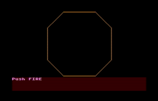
1. The opening screen shows the outer wall. Press the FIRE button to start.
2. You control the white +-shaped ship with your joystick. The three rogue atomic particles start on the other side of the core.
3. The particles do a random-walk while seeking out your ship. The bounce off of each other when they collide.
4. Gain points by hitting the particles with your ship.
5. The reactor core grows over time pushing your ship and the particles towards the deadly wall.
6. Use your ship to bump the particles towards the outer wall.
7. Be careful because the particles can bump you towards the wall, too! You have 5 lives.
8. Bump the particle into the wall to destroy it.
9. Two win, bump all three particles into the wall before the core swells too big!
Here's the compressed 10-line code:

Let's dig into the code:
data D() WORD = -1,1,2,2,1,-1,-2,-2,-1,1,2 Array to store info to draw an octagon. The drawing routine is at the bottom of the listing.
data x() WORD = 0,10,0,-10,0
data y() WORD = -20,20,20,20,0
Arrays to store X and Y positions of sprites with initial positions. Fifth index is the origin so I can reuse physics code.
dim alive(4), colsnX(4), colsnY(4) Arrays that store alive/dead state of PM's and changes in position due to collisions.
numkilled = 0
numlives = 5
score=0
rate = 15
counter = rate-1
Initialize some counters.
graphics 7
poke 752,1
Use 4 color 160x80 mode
Turn off cursor in text window
PM=$A000 mset $a000,1024,0
poke 54279,PM/256
poke 53277,3
poke 559,46
Clear out some RAM
 Tell ANTIC where PM RAM is' Enable PM display
Enable PM DMA with 2-line res
dpoke 704,$440F
dpoke 706,$4444
dpoke 709,$404F
Set colors for players 0 and 1,
players 2 and 3, and
the text window
x0=80
y0=40
color 1
radius = 19
exec octagon
Store the coordinates for the center of the screen.
Pick color 1, default is orange
Set the radius to draw the large octagon. Call the routine at the end of the listing.
?"Push FIRE" WHILE STRIG(0):WEND CLS Wait for player to start the game.
WHILE numkilled < 3 AND numlives> 0 This begins the main game loop
  alive(0) = 0 Reset the player is still alive flag.
  inc counter
  setcolor 1,counter,15
  if counter MOD rate = 0
    color 2
    radius = counter/rate
    exec octagon
  endif
Take care of the background graphics. Increment a counter to rotate the colors using the SETCOLOR command. Draw a larger octagon to enlarge the core every RATE game loop cycles. The EXEC OCTAGON jumps to the drawing routine at the end of the listing.
  poke 53248,x0+44+X(0)
  move adr(" -stuff-")+1, PM+$200 + y0 + 9 + Y(0), 17
Move player location. Poke the X coordinate and MOVE memory for the Y coordinate. The sprite is defined by the string, which starts at one byte higher than the address in FastBasic.
  for i=1 to 3
    move adr(" ball " ) + 1, PM + $200 + i*128 + y0 + 9 + Y(i), 14
    poke 53248+i,(x0+43+X(i))*(alive(i)=0)
  next i
Loop to move each  particle location. If particle is dead, keep it off the screen.
  poke 53278,1
  PAUSE 1
Clear collision register and paint the screen once to record collisions.
  for i=0 to 3 Loop through all the PM's
    colsnX(i) = 0
    colsnY(i) = 0
Initialize the collision accumulators...
    PiPF = peek(53252+i) Check the player-player collision register.
    if PiPF&1 = 1
      alive(i) = 1
Someone hit the wall! Set the alive/dead flag.
      if i = 0
        X(i) = 0
        Y(i) = -2*radius
        dec numlives
        mset PM+$200,128,0
        exit
It was the player's ship. Reset it's position and take away a life. Exit the collision detection loop.
      else
        X(i) = -43-x0
        inc numkilled
      endif
It was a particle. Kill it and remove it from the screen.
    elif PiPF&2 = 2
      freq = 80
      j=4
      exec bounce
    endif
Something hit the core. Make it bounce and get ready to play a tone.
    PiPj = peek(53260+i) Now check for player collisions. The 'i' value is subject player and 'j' value is player that was hit.
    if PiPj > 0 Act if there was a collision.
      if PiPj&1 = 1
        freq = 40
        j = 0
        score=score+5
The ship made a hit. Get some points and get ready to play a high-pitched tone.
      elif PiPj&2 = 2
        j = 1
      elif PiPj&4 = 4
        j = 2
      elif PiPj&8 = 8
        j = 3
      endif
Check for collisions with the particles.
      exec bounce Compute bounce position change.
    endif
  next i
Close the loop.
  if freq>0
    sound 0,freq,10,15
  else
    sound
  endif
  freq = 0
Play a tone or stop the tone, if needed.
  for i=1 to 3
    X(i)=X(i) - SGN((X(i)-X(0))/10) + colsnX(i) + RAND(3)-1 -(X(i)/33)
    Y(i)=Y(i) - SGN((Y(i)-Y(0))/10) + colsnY(i) + RAND(3)-1 -(Y(i)/33)
  next i
Update particle locations: attract to player, add in the bounce, do a little random walk, and stay away from the walls.
  P.657,2
  ? score, numlives;
Update the scoreboard. The POKE command positions the cursor before printing to the screen.
  S=STICK(0)
  LR=(S&4=4)-(S&8=8)
  UD=(S&1=1)-(S&2=2)
  Y(0) = Y(0) + colsnY(0) + UD+UD
  X(0) = X(0) + colsnX(0) + LR+LR
Get joystick input and move the player. Also add in the player bounce move.
WEND End of game loop.
SOUND Game over. Stop the sound.
if numkilled=3 and alive(0)=0 
  ?;"You Win!";
else
  ?;"/MELTDOWN\";
endif
Figure out the result.
do
loop
Wait forever.
proc bounce
  colsnX(i) = colsnX(i) + 2*SGN(X(i)-X(j))
  colsnY(i) = colsnY(i) + 2*SGN(Y(i)-Y(j))
endproc
Procedure to add in bounce motion. The motion is towards the ith particle and away from the jth particle. When j=4, the motion is away from the origin.
proc octagon
  plot x0-radius, y0 + 2*radius
  for p = 1 to 8
    drawto x0 + D(p)*radius, y0 + D(p+2)*radius
  next p
endproc
Procedure to draw an octagon. Loop through the vertices and draw lines. Scale the size by 'radius.'